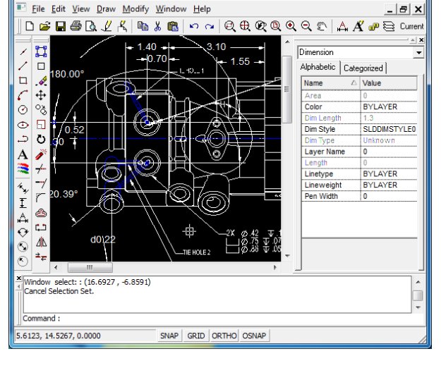

For example if you type command polyline and draw at least two segments you get prompted Specify next point or. They tell you what input they expect - a point for example - and list other possibilities in the square bracket. Many commands prompt you on the command line asking for further input. If you type too short a segment of a command, such as c and press Tab, the command output will show "ch, circle, cut" because the command segment you typed in isn't unique.

It is possible to enter a partial command, like cir and press Tab to have the command completed to circle. You press the Escape key to leave the command line and another Escape to cancel what you have written on the command line. So now when you press a key you are entering commands. When the command line is active the "Command:" (left of where input appears) turns blue. Using the Command line You can press the Space-bar or to activate the command line. LibreCAD is designed with emphasis on mouse-clicking input, and some options can be at the moment only selected by clicking, not by typing on command line. This can be faster and/or more precise than drawing using exclusively a mouse and tool bars. See also: Autogenerated API documentation and FreeCAD Scripting Basics.1 Introduction This is intended for people that want to draw by entering commands. View End Arrow ( Bool): specifies whether to show a symbol at the end of the fillet, so it can be used as an annotation line.View Arrow Type ( Enumeration): specifies the type of symbol displayed at the end of the fillet, which can be Dot, Circle, Arrow, Tick or Tick-2.View Arrow Size ( Length): specifies the size of the symbol displayed at the end of the fillet.Data Start ( VectorDistance): (read-only) specifies the start point of the fillet.Data Length ( Length): (read-only) specifies the total length of the fillet.Data Fillet Radius ( Length): (read-only) radius with which the fillet was created.Data End ( VectorDistance): (read-only) specifies the end point of the fillet.It also has the following additional properties:
LIBRECAD FILLET UPGRADE
Since Draft Lines and Draft Wires, can be joined with the Draft Wire command, the Draft Join command or the Draft Upgrade command, this provides an alternative method for creating fillets and chamfers.Ī Draft Fillet object is derived from a Part Part2DObject and inherits all its properties. A Draft Wire that has at least three points can be filleted or chamfered by changing its Data Fillet Radius or Data Chamfer Size respectively.Only Draft Lines, that is Draft Wires with only two points, are supported at the moment.A Draft Fillet cannot be edited nor is it linked to the lines that were used to create it.Press Esc or the Close button to abort the command.If you have selected one of the two previous options: Click in the Fillet radius input box.Optionally check the Create chamfer option.Optionally check the Delete original objects option.Note that the command will not succeed if the radius or the chamfer size is too large for the selected lines. If the Create chamfer option is selected this will be the size of the chamfer (the length of the straight edge). Select the Drafting → Fillet option from the menu.

There are several ways to invoke the command:.Select two Draft Lines that meet in a single point.Several fillets and chamfers created between two lines Usage The Draft Fillet command creates a fillet, a rounded corner, or a chamfer, a straight edge, between two Draft Lines.


 0 kommentar(er)
